
Details
| Surface Treatment |
Anodized |
Material |
Carbon steel Mg-Al-Zn Coating / Hot-dip galva ized |
| Place of Origin |
China |
Installation Site |
Open Field |
| Brand Name |
Exten |
Model Number |
A02-1 |
| Standard |
|
Certificate |
AS/NZS1170.2/CE/ISO |
| Wind Load |
60m/s(196.85ft/s) |
Module Orientation |
Landscape Portrait |
| Wind speed |
Yo 60m/s |
Max Snow Load |
1.4KN/m2 |
| Snow Load |
1.4KN/m2(29.24psf) |
Service Life |
25YRS |
Component List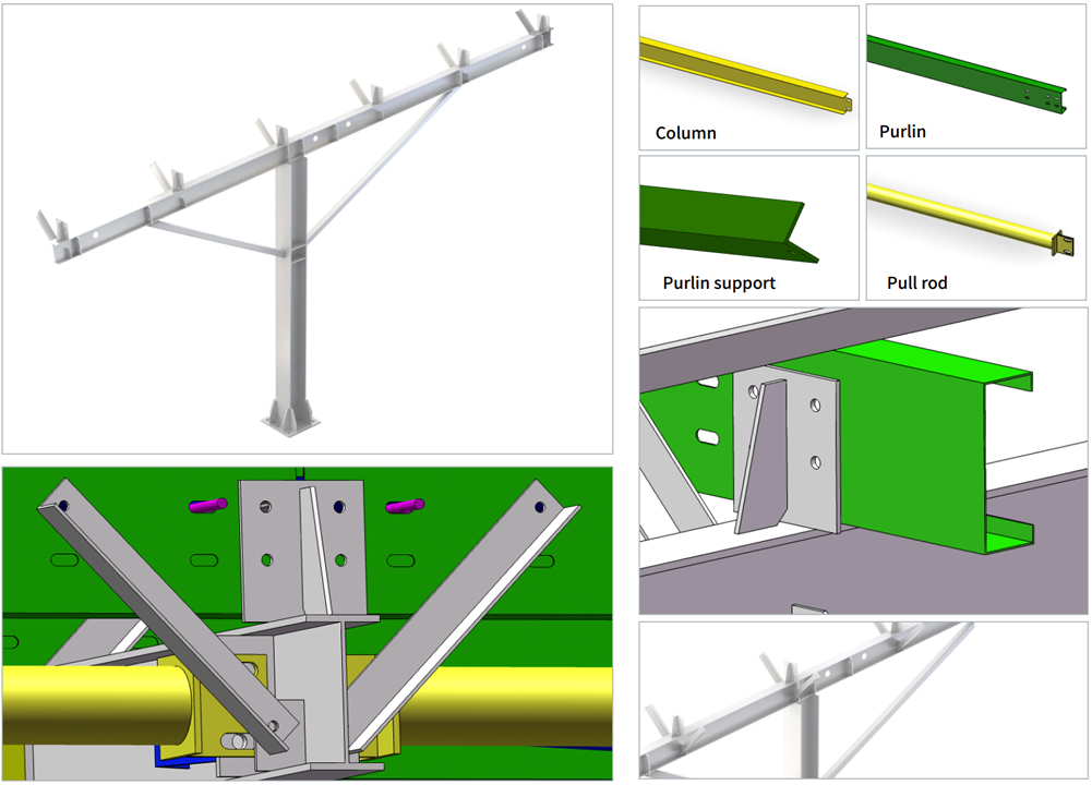
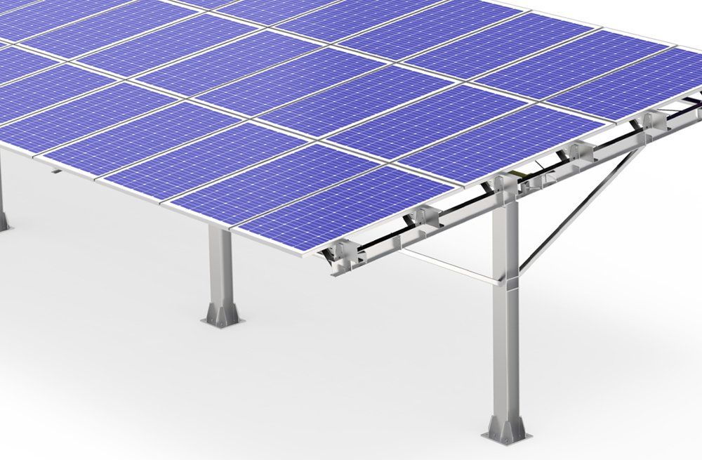
Single-Row Steel Frame Carport Solar Mounting System Overview
What is single-row steel frame carport solar mounting system? Thanks to its high strength-to-weight ratio, mature welding techniques, and flexible span capabilities, the steel-frame system enables greater overhangs and fewer columns in a single-row layout. The content covers a breakdown of core advantages, five on-site practical FAQs, and a standardized installation process from foundation excavation to grid connection and commissioning.
Aluminum Alloy Solar Carports Advantages
Significant advantages in load-bearing capacity and span. The yield strength of steel is far higher than that of aluminum alloy, allowing the main beam of a single-row carport to easily achieve a cantilever length of 5 meters or even over 6 meters, while column spacing can be widened to approximately 8 meters. This means that for the same number of parking spaces, the number of pile foundations is reduced, and the volume of earth excavation and concrete pouring decreases accordingly. This reduction significantly enhances construction efficiency, particularly on sites with hard soil or complex underground utility lines.
Flexible on-site adjustments and strong adaptability. The steel frame structure supports on-site cutting, drilling, and welding adjustments. If underground obstacles not identified during geological surveys are encountered, engineers can modify column positions or adjust main beam connection angles on the same day. This flexibility significantly reduces schedule delays caused by design changes, particularly for projects with undulating terrain or irregular boundaries.
The corrosion protection system is mature and reliable. The hot-dip galvanized coating typically exceeds 85 micrometers in thickness. Combined with a composite coating of zinc-rich epoxy primer and polyurethane topcoat, it remains rust-free for over 20 years even in C5-class corrosive environments. Furthermore, the natural surface roughness of the steel frame provides excellent adhesion for the coating; during later maintenance, only localized sanding and touch-ups are required, unlike certain materials that require a complete recoating.
The system offers strong cost competitiveness and a stable supply chain. Processing technologies for hot-rolled steel sections and welded H-beams are extremely mature, with processing costs per metric ton approximately 40% lower than those of aluminum alloys of the same specifications. Material procurement channels are extensive, and delivery cycles typically do not exceed two weeks—a very practical advantage for projects with tight schedules.
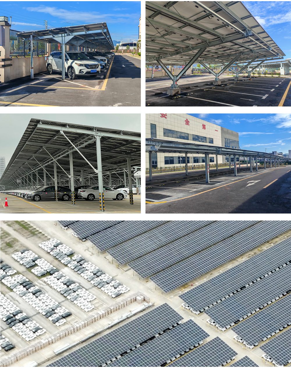
Case
Installation Process
Step 1: Site Survey and Foundation Layout
Use a total station to survey the site’s elevation and mark the locations of underground utilities and obstacles. Lay out the center points of the columns according to the construction drawings, marking each point with a wooden stake and red paint, with a lateral deviation not exceeding 5 millimeters. At the same time, verify the installation locations of the inverters and grid-connection cabinets to ensure the DC cable routes are as short as possible and do not cross with other utility lines.
Step 2: Foundation Construction and Anchor Bolt Positioning
Excavate the foundation pit according to the geological report; the depth and diameter depend on wind loads and soil conditions, typically ranging from 1.2 to 1.8 meters. After pouring a plain concrete base layer at the bottom of the pit, tie the reinforcing cage. When installing anchor bolts, use positioning plates to secure them, keeping the deviation in the exposed height of the bolt heads within ±2 millimeters. The concrete grade must be no less than C30. The curing period must be at least 7 days, and the structure may not be loaded until the concrete reaches 75% of its design strength.
Step 3: Hoisting of Steel Columns and Installation of Main Beams
After the steel columns are hoisted into position, first slide them onto the anchor bolts and tighten the nuts without fully locking them. Use a theodolite to check the verticality of the columns, ensuring the deviation is within one thousandth. Next, hoist the main beams into place. Connect the beams to the columns using high-strength bolt assemblies. After applying an initial torque of 50% of the final torque value, release the crane. Once all beams are in position, apply the final torque uniformly to the design value.
Step 4: Installation of Purlins and Bracing System
Lay the transverse purlins according to the spacing specified in the drawings, and install anti-loosening washers at the bolted connections. Simultaneously, install the cross-bracing between columns and the horizontal roof bracing; secure both ends of all bracing rods with double nuts. At this stage, re-measure the flatness of the purlin upper surface; the height difference between any three adjacent points must not exceed 3 millimeters, otherwise it will affect the stress distribution during subsequent component installation.
Step 5: PV Module Installation and Wiring
Begin installing the modules from one end of the carport. Secure each module to the purlins using four aluminum alloy clamps, ensuring the torque of the clamp bolts is maintained within the range of 18–22 Newton-meters. Leave a 10- to 15-millimeter gap between modules to accommodate thermal expansion and contraction. Route the DC cables through the protective conduits pre-installed along the inner walls of the main beams. Before connecting, wipe the terminals of the MC4 connectors with a specialized cleaner to ensure contact resistance is less than 0.35 milliohms.
Step 6: Grounding System Installation and Insulation Testing
Lay galvanized flat steel along the entire length of the carport to serve as the main grounding busbar. Each steel column must be securely welded to the grounding electrode via the flat steel, with the weld length being no less than twice the width of the flat steel. Measure with a ground resistance tester; the resistance value must be less than 4 ohms. Use a megohmmeter to test the insulation resistance between the positive and negative terminals of each string and ground. In dry weather, the value should not be less than 50 megohms; in humid weather, it should not be less than 10 megohms.
Step 7: Inverter Connection and System Commissioning
Connect the output terminals of the combiner box to the DC side of the inverter. After confirming the polarity is correct, close the DC switch. After powering on the inverter, observe the voltage and current readings on the display to confirm that MPPT tracking is functioning normally. Gradually increase the load to 50%, 75%, and 100% of the rated power. Allow the system to operate stably under each condition for at least 10 minutes, and record the power generation parameters. Finally, test the anti-islanding protection function by disconnecting the grid to simulate a power outage; the inverter should automatically shut down within 0.2 seconds.
Step 8: Acceptance, Handover, and Documentation
Clear all waste materials and packaging from the construction site and dismantle temporary facilities. Prepare a complete set of as-built documentation, including structural calculation reports, weld inspection reports, ground resistance test records, inverter commissioning logs, and operation and maintenance manuals. Conduct an on-site acceptance inspection jointly with the owner, verifying each item—including bolt torque markings, cable bundling procedures, and drainage slopes—on a point-by-point basis. Complete the project handover after both parties have signed off on the inspection.
FAQ
Q1: Will a steel-frame carport be too heavy, leading to excessive foundation costs?
While the dead weight of a steel frame is indeed greater than that of aluminum alloy, optimizing the truss or honeycomb beam design can limit steel consumption to 35–45 kg/m². The increase in foundation load is minimal, and most sites will not require additional excavation.
Q2: Will welded joints become weak points prone to fatigue?
Critical load-bearing joints use full-penetration groove welding and undergo ultrasonic testing. Fillet weld dimensions are increased by one grade according to specifications, fatigue life calculations cover 25 years of cyclic loading, and joint strength is no less than that of the base material.
Q3: What should be done if the galvanized coating is scratched during transportation?
Apply cold-galvanized touch-up paint to the damaged areas on-site. The dry film thickness must be no less than that of the original galvanized coating, and the structure is ready for use once adhesion tests meet the standards; there is no need to return the structure to the factory for re-galvanizing.
Q4: Do single-row steel frames require additional reinforcement in high-wind areas?
Column bases use rigid connections rather than hinged joints, and round steel cross-bracing is installed between columns. This significantly enhances lateral stiffness, meeting the requirements for a basic wind speed of 40 m/s.
Q5: Can the steel frame support an increase in photovoltaic capacity at a later date?
A 20% load capacity margin is built into the design. Purlin spacing and connection hole positions are pre-arranged according to double-glass module specifications; later on, only the module model needs to be replaced, with no structural modifications required.


